The Axis page offers many capabilities including: axis motion, status, and configuration.
.png) Axis Screen
Axis Screen
🔹 Axis Status
Read your axis' status in real-time.
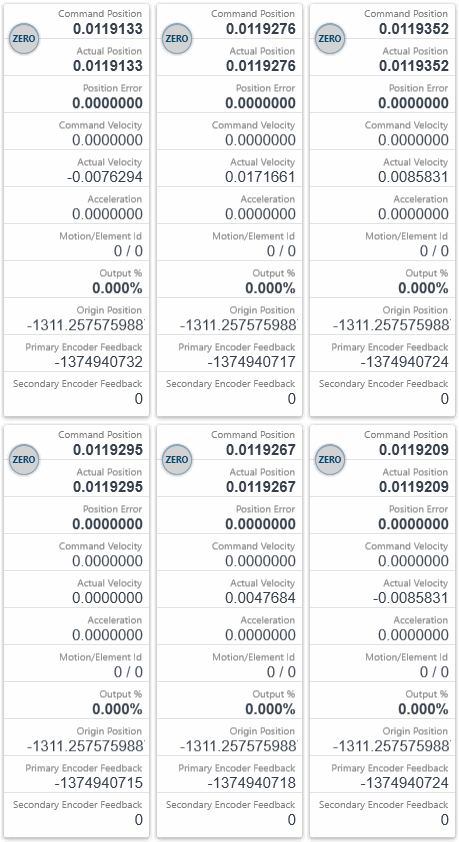
- Command Position displays the instantaneous commanded position by the controller.
- Actual Position displays the instantaneous actual position of the primary feedback device on the motor. (This can also be pointed to the secondary feedback when in dual loop mode)
- Position Error displays the instantaneous difference between command and actual.
- Command Velocity displays the instantaneous commanded velocity by the controller.
- Actual Velocity displays the instantaneous actual velocity of the primary feedback device on the motor. This can also be pointed to the secondary feedback when in dual loop mode.
- Acceleration displays the instantaneous commanded acceleration by the controller.
- Motion/Element Id displays the motion identifier of the current move if one is set. Element ID if it is streaming motion.
- Output % displays the instantaneous command percentage. (Torque Mode only.) The output percent ranges from -100% to + 100% correlating to the full 16 bit range of -32767 to +32767 counts. The output % can be capped by reducing the OutLimitHi and OutLimitLow settings in the tuning parameters tab.
- Origin Position is the internal offset applied such that Command Position = Feedback Position - Origin Position.
- Primary Encoder Feedback is the raw position from the feedback device on the drive.
- Secondary Encoder Feedback is also a raw position from the secondary (optional) feedback on the drive.
- Zero Button sets the command and actual positions to 0. (Internally it sets the Origin Position.) This will void any axis homing and will set the HomeState to false. You cannot set the position when the state is MOVING, STOPPING or STOPPED.
🔹 Axis Motion
Take control of your axis' motion.
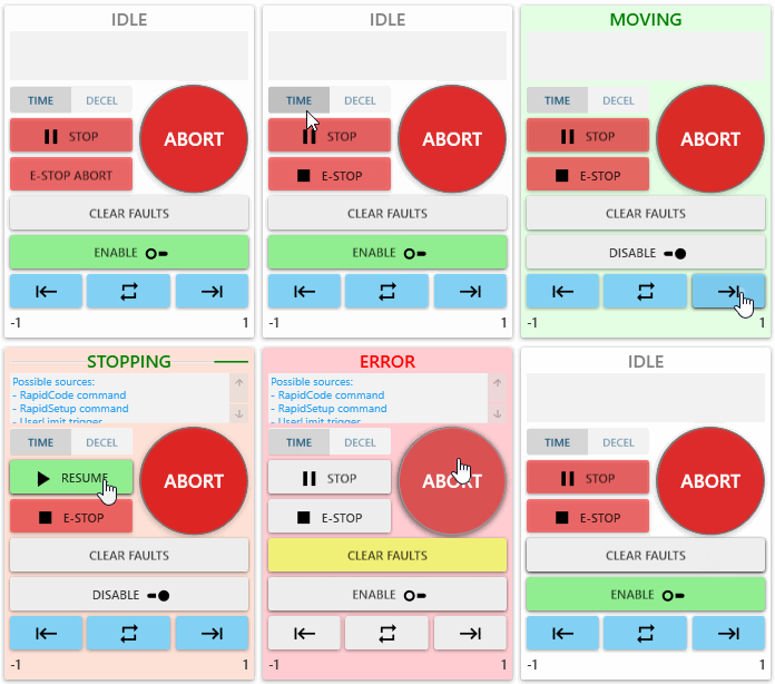
- Axis State Label Error, Idle, Moving, Stopping, Stopped, or Stopping Error.
- Axis Error Source Block will display the source of the axis error if there is one.
- Time & Decel Buttons allow you to change between time-based stops and deceleration-based stops.
- Stop Button pauses your axis' motion. (Configure stop speed in Settling Criteria tab.)
- Resume Button resume your axis' motion (only valid when state is STOPPED).
- E-Stop Button quick stops your axis motion and puts you on ERROR state. (Configure e-stop speed in Settling Criteria tab)
- Abort Button will stop any motion and put you in error state.
- Clear Faults Button allows you to clear the fault when the axis is in an Error state. If successful, the axis will change to Idle. Else, then there is an error which cannot be cleared. Check the error message or axis error source to resolve the conflict.
- Enable Button allows yo to enable the amplifier so power is applied to the motor.
- Disable Button allows you to disable the amplifier so motor power is removed.
- Motion Buttons
- If Absolute motion profile is selected, allows you to go back and forth between Position 1 and Position 2.
- If Relative motion profile is selected, allows you to move up or down by the specified Increment value.
- If Velocity motion profile is selected, allows you to command positive or negative velocity move using the specified velocity.
- Left Label displays Position 1.
- Right Label displays Position 2.
🔹 Motion BITS & Status BITS
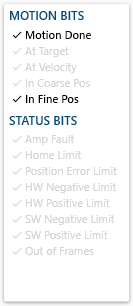
- Motion Done Bit returns true when the commanded motion is complete and the axis has settled. (see the Settling Criteria tab)
- At Target Bit returns true when the command position reaches the final commanded position of the move.
- At Velocity Bit returns true when the axis reaches the maximum velocity specified.
- In Coarse Pos Bit returns true when the commanded motion reaches the Coarse Position Tolerance (c*onfigure in Settling Criteria tab*).
- In Fine Pos Bit returns true when the actual position is within the value of Fine Position Tolerance (configure in Settling Criteria tab).
- Amp Fault Bit returns true when the fault is from the servo amplifier.
- Home Limit Bit returns true when the Home Limit is triggered.
- Position Error Limit Bit returns true when the Position Error Limit is triggered. (see Limits and Actions tab)
- HW Negative Limit Bit returns true when the Hardware Negative Limit is triggered. (see Limits and Actions tab)
- HW Positive Limit Bit returns true when the Hardware Positive Limit is triggered. (see Limits and Actions tab)
- SW Negative Limit Bit returns true when the Software Negative Limit is triggered. (see Limits and Actions tab)
- SW Positive Limit Bit returns true when the Software Positive Limit is triggered. (see Limits and Actions tab)
- Out of Frames Bit returns true when a streaming (PT, PVT) motion runs out of frames because a user hasn't loaded enough points in advance.
🔹 Status Word BITS
The DS402 status word indicates the current status of the drive.
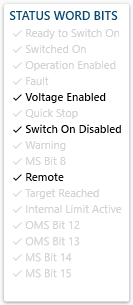
- Ready to Switch On Bit: high voltage may be applied to the drive. The drive parameters may be changed. The drive function is disabled.
- Switched On Bit: high voltage has been applied to the drive. The power amplifier is ready. The drive parameters may be changed. The drive function is disabled.
- Operation Enabled Bit: no faults have been detected. The drive function is enabled and power is applied to the motor. The drive parameters may be changed. (This corresponds to normal operation of the drive.)
- Fault Bit: the drive parameters may be changed. A fault has occurred in the drive. The drive function is disabled.
- Voltage Enabled Bit: voltage has been applied to the drive.
- Quick Stop Bit: the drive parameters may be changed. The Quick Stop function is being executed. The drive function is enabled and power is applied to the motor
- Switch On Disabled Bit: drive initialization is complete. The drive parameters have been set up. Drive parameters may be changed. High voltage may not be applied to the drive, (e.g. for safety reasons). The drive function is disabled.
- Warning Bit When the bit is 1, it means the servo drive detects alarm.
- MS Bit 8 Reserved
- Remote Bit Means Controlword can be deal with
- Target Reached Bit: homing positioning target has been reached.
- Internal Limit Active Bit When this bit is 1, it means that the internal torque has surpassed the set value, or machine has run into external positive /negative limit switch.
- OMS Bit 12 is a drive specific bit.
- OMS Bit 13 is a drive specific bit.
- MS Bit 14 is a drive specific bit.
- MS Bit 15 is a drive specific bit.
🔹 Dedicated I/O
Set the trigger state accordingly under the Limits and Actions tab.
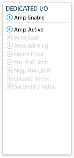
- Amp Enable represents the state of the Amp Enable output
- Amp Active represents the state of the Amp Active input.
- Amp Fault represents the current state of the Amp Fault input.
- Amp Warning represents the state of the Amp Warning input.
- Home Input represents the current state of the Home switch input.
- Pos. HW Limit represents the state of the Hardware Positive Limit .
- Neg. HW Limit represents the state of the Hardware Negative Limit input.
- Encoder Index represents :::
- Secondary Index represents :::
🔹 Subsections
- Configuration : Configure motor type, operation mode, backlash, and encoder ratio of an axis.
- Limits And Actions : Configure the triggers and response actions for position error limits, software limits, hardware limits, home triggers, amp faults, and user faults.
- Motion : Discover some of the different types of motion provided by our RapidCode API.
- Electronic Gearing : Gearing links two or more axes such that the position of the “slave” axis is a function of the position of the “master” axis.
- Homing : Drive based homing is recommended over master based since drive based homing does not encounter network latency.
- Settling Criteria : Configure the triggers for various motion interrupts.
- Tuning : Tune an axis that is set to torque mode (only available in Expert Mode).
- Akd Ascii : Quick and easy way to issue commands to the AKD drive directly.


.png) Axis Screen
Axis Screen


