Learn how to spin an axis with the RapidSetup tool.
- Warning
- Safety First
Kindly implement essential safety measures to safeguard both yourself and those around you. Feel free to reach out to us for tailored guidance on enhancing the security of your system.
- Precondition
- Your EtherCAT network must be OPERATIONAL. Follow the RapidSetup Start the network guide.
- RapidSetup tool is running.
🔹 Configure Axis Settings
1. Set up a free spinning motor
- Verify that the motor can safely be spun (we recommend an uncoupled axis to start).
- In the tree view, navigate to any Axis item that is available.

- Set the “User Units”
This will convert our position into terms of revolutions.
- If you know the counts per revolution of your encoder: enter that value into the User Units field.
- If you don't: use the procedure shown at 🔹 Estimate Encoder Resolution under the RapidSetup tab.
- Next, navigate to the Limits and Actions Tab.
- Set the POSITION ERROR Action to ABORT and set the Trigger Value to 1.0. The Position error trigger value is scaled by the counts per unit you just entered. Assuming the User Units entered correlate to 1 motor revolution, this will allow for 1 motor revolution of the following error.
.png)
- (Optional) Set the POSITIVE & NEGATIVE HARDWARE actions to NONE since there is no mechanical end-of-travel limit.
- (Optional) Connect to the drive using the manufacturer’s drive interface GUI and tune the position loop. Many manufacturers offer a quick auto-tuning feature. Some drives even have default tuning gains selected and you can skip this step for now.
2. Set up a coupled motor (Only if it applies to you)
- Connect both the Positive and Negative limit switches (EOT – end of travel sensors) to the drive according to the drive manual. This will minimize the risk of damaging your equipment. The EOT sensors should be placed far enough inside the physical end-stops of the axis so that the axis has enough distance to decelerate from full speed before crashing into the end-stops.
- Verify that the limit switches are working and getting read correctly through the network. You can see the state of the limit switches under the Dedicated I/O tab in RapidSetup shown below. Make sure you can trigger them by hand and watch the state change when the sensor is activated.
.png)
- Navigate to the Limits and Actions tab. If your limit sensors are normally low and active high (like the picture above), then the trigger state high checkbox must be checked. Change the action to ABORT for both positive and negative hardware limit sensors.
.png)
- Click the CLEAR FAULTS button and all the Faults should go away and the axis should go to an IDLE state.
.png)
- Trigger the EOT sensors by hand. This should cause an ABORT. If it doesn’t, check the sensor wiring. Also under the Limits and Actions tab, verify the trigger state high checkbox is set correctly and that the actions are set to ABORT for both Positive and Negative Hardware limits.
- If you can move the axis by hand to the middle of its range of motion.
- Calculate the “Counts per Unit” for your preferred linear units and enter it under the “Motion and Tuning” tab. See Examples on the Calculate Counts per Unit Topic page.
Navigate back to the Limits and Actions Tab. Set the Position Error Action to ABORT and set the Trigger Value to something reasonable for your machine. The Position Error Trigger value is scaled by the counts per unit you just entered.
- Note
- Example
The stroke length of a Ballscrew is 5 ft. After moving the slide to the center, I have about 2.5 feet in the positive direction and 2.5 feet in the negative direction. I’d set the position error to 1 inch so the axis will abort before it can run away.
- Failing to do these critical steps could be a safety risk or could result in damage to your equipment.
- Connect to the drive using the manufacturer’s drive interface GUI and tune the position loop. Many manufacturers offer a quick auto-tuning feature. Some drives even have default tuning gains selected and you can skip this step for now.
🔹 Spin the Axis
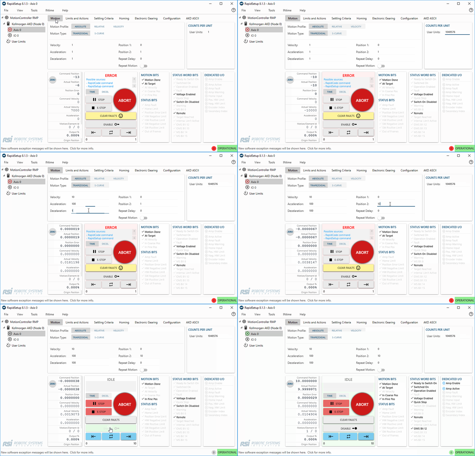
- In the Motion tab, set your motion parameters for a move that makes sense for your system. See example parameters below:
| Field | Value |
| Velocity | 3 rev/s |
| Acceleration | 2 rev/s2 |
| Deceleration | 2 rev/s2 |
| Position 1 | 0 revolutions |
| Position 2 | 10 revolutions |
- Select which type of motion you’d like to command by selecting either Absolute, Relative, Velocity under the motion profile section:
.png)
- Zero the position of the axis

- Click the CLEAR FAULTS button, then click the ENABLE button.
.png)
- Assuming the motor is tuned by the drive and your Axis has been enabled, you can start commanding motion. Use these three arrows to move the motor back and forth.
.png)
🔹 Gif Example


.png)
.png)
.png)
.png)
.png)

.png)
.png)
