APIs, concepts, guides, and more
NodeInfo & CustomNodeInfo files

See, add, or customize EtherCAT node info.


The RMP motion controller provides a more streamlined and unified way to interact with the various types of EtherCAT nodes/subdevices with the RapidCode API.

From a software perspective, all RapidCode Axis and IOPoint objects behave the same regardless of manufacturer. This minimizes the amount of changes to your software application that would be required if you have to swap drive manufacturers.

🔹 What are these files?

📄 NodeInfo.xml

Contains all RSI officially supported/integrated EtherCAT nodes as of RMP version 10.5.5.

  • NOT EDITABLE
  • Lists all supported EtherCAT nodes. (Can also be seen here)

See info about Settings section (only if RSI has recommended this)
You need to use NodeInfo.xml for the <Settings> block for everything, but <StrictNodeOrder>. This block handles automatic identification of IO based on size and key strings. By default, all 1 bit sized PDO entries are assumed to be Digital Inputs or Digital Outputs. This leads some Diagnostics and Control bits being identified as IO when you don't desire it. Add <Ignore> entries remove false positive identifications. Analog values are harder to detect. In order to add them, add an appropriate <AnalogInput> or <AnalogOutput> block following examples within the file.

The Has attribute can be used to add an additional string to help identify the IO.

Example
<AnalogInput Size="16" Has="(Beckhoff - AI">.Value</AnalogInput> will search for a pdo entry with both (Beckhoff - AI and .Value in it.

📝 CustomNodeInfo.xml

Allows users to add new nodes or customize existing nodes to meet your application needs.

  • EDITABLE
  • Available starting RMP version 10.4.2
  • Vendor entries in CustomNodeInfo.xml will fully replace Vendor entries in NodeInfo.xml

See file

Many comments where added to explain all possible entries.

<EtherCATNodeInfo>
<!-- Comments to help you implement your own changes have been added. -->
<!-- Please reference https://support.roboticsys.com/nodeinfo.html for additional information. -->
<Vendors>
<!-- Required - Vendor: Add the Vendor of the Node you are trying to edit or modify. -->
<!-- Required - Id: This must match the one displayed on RapidSetup's Node page. -->
<Vendor Id="0x111713">
<!-- Required - VendorName: Can be anything but we recommend you use the one in the ESI file. -->
<VendorName>Robotic Systems Integration</VendorName>
<!-- Required - Product: One or more Product elements which describe the node. -->
<!-- Required - Code: This must match the one displayed RapidSetup's Node page. -->
<!-- Optional - Pattern: See Patterns block located at the Vendors level. -->
<Product Code="0xdead" Pattern="FakePatternName">
<!-- Required - ProductName: Can be anything but we recommend you keep the value specified in the ESI file. -->
<ProductName>Not a Real Node</ProductName>
<!-- Required - ShortName: Determines RapidSetup's node name. We recommend the [Vendor Name Product Name] -->
<ShortName>RSI FakeNode</ShortName>
<!-- Required - ItemSubType: Can be Drive, Box, or Term. -->
<ItemSubType>Drive</ItemSubType>
<!-- Optional - IO: Allows you to specify IO when it is not automatically detected. -->
<IO>
<!-- Optional - DigitalInputItems: Add in PDOEntries you want to be identified as Digital Inputs. -->
<DigitalInputItems>
<!-- Required - DigitalInput: One or more entries to evaluate. -->
<!-- Required - SigBits: Specific which bits in the associated PDO entry are treated as IO. This is a bit mask. Most DS402 IO starts in the upper 4 bytes. -->
<!-- Required - Size: (In bits) Normally this will be 8, 16, or 32 -->
<!-- Optional - Home | PosLimit | NegLimit: (Bit Index) Represent DedicatedIO which are automatically tied in with RSI events associated with the axis. -->
<!-- Required - Value: String to help us find the associated PDO Entry. -->
<DigitalInput SigBits="0x007F0000" Size="32" Home="16" PosLimit="20" NegLimit="21">Inputs.Digital inputs</DigitalInput>
</DigitalInputItems>
<!-- Optional - DigitalOutputItems: Add in PDOEntries you want to be identified as Digital Outputs. -->
<DigitalOutputItems>
<!-- Required - DigitalOutput: One or more entries to evaluate. -->
<!-- Required - SigBits: Specific which bits in the associated PDO entry are treated as IO. This is a bit mask. Most DS402 IO starts in the upper 4 bytes. -->
<!-- Required - Size: (In bits) Normally this will be 8, 16, or 32 -->
<!-- Required - Value: String to help us find the associated PDO Entry. -->
<DigitalOutput SigBits="0x00030000" Size="32">Outputs.Digital outputs</DigitalOutput>
</DigitalOutputItems>
<!-- Optional - AnalogInputItems: Add in PDOEntries you want to be identified as Digital Outputs. -->
<AnalogInputItems>
<!-- Required - AnalogInput: One or more entries to evaluate. -->
<!-- Required - Size: (In bits) Normally this will be 8, 16, or 32 -->
<!-- Required - Value: String to help us find the associated PDO Entry. -->
<AnalogInput Size="16">Inputs.AIN.VALUE</AnalogInput>
</AnalogInputItems>
<!-- Optional - AnalogOutputItems: Add in PDOEntries you want to be identified as Digital Outputs. -->
<AnalogOutputItems>
<!-- Required - AnalogOutput: One or more entries to evaluate. -->
<!-- Required - Size: (In bits) Normally this will be 8, 16, or 32 -->
<!-- Required - Value: String to help us find the associated PDO Entry. -->
<AnalogOutput Size="16">Outputs.AOUT.VALUE</AnalogOutput>
</AnalogOutputItems>
</IO>
<!-- Optional - InitCmds: Commands you want to add to the startup process of each drive. -->
<InitCmds>
<!-- Required - InitCmd: One or more InitCmds to inject. -->
<!-- Required - Index: Address of the value you want to set. -->
<!-- Required - SubIndex: SubAddress of the value you want to set. -->
<!-- Required - Transition: Timing of when the InitCmd happens in the startup process. Valid Transitions are IP(init -> pre-op), PS(pre-op -> safe-op), and SO(* -> Operational). -->
<!-- Required - Value: The data in the InitCmd is done in reverse byte order. 0xabcdef would be represented as ef cd ab 00 -->
<InitCmd Index="0x60FE" SubIndex="0x2" Transition="SO">ef cd ab 00</InitCmd>
<!-- Another example... -->
<!-- Optional - ChangeData: Change the data from 0xabcdef to 0x12345678-->
<!-- Optional - ChangeTimeout: Change the timeout for the InitCmd-->
<!-- Optional - ChangeTransition: Change the Transition from SO to PS-->
<InitCmd Index="0x60FE" SubIndex="0x2" Transition="SO" ChangeData="78 56 34 12" ChangeTimeout="1000" ChangeTransition="PS">ef cd ab 00</InitCmd>
</InitCmds>
<!-- Optional - PDOs: Change the default ESI defined exchanged values. -->
<PDOs>
<!-- Required - PDOAssignment: One or more PDOs to adjust, add, or remove. -->
<!-- Required - Index: Index of the PDO you want to adjust. -->
<!-- Required - IsOutput: Output or Input from the MainDevice's perspective not the node's. -->
<!-- Required - Include: Determines if you are removing the PDO (false) or including/modifying it (true) -->
<PDOAssignment Index="0x1B01" IsOutput="False" Include="False"/>
<!-- Another example... -->
<!-- Optional - RemoveContent: Strip out any PDO Entries you want from existing PDO defaults. -->
<!-- RemoveContent - Detail: Format is "0x####(space)0x####(space)0x####" -->
<!-- RemoveContent - Note: Some PDOs are fixed and cannot be modified. -->
<PDOAssignment Index="0x1A00" IsOutput="False" Include="True" RemoveContent="0x6041 0x6042" />
<!-- Another example... -->
<PDOAssignment Index="0x1A01" IsOutput="False" Include="True">
<!-- Optional - AddEntry: One or More new PDO entries to an existing PDO. -->
<!-- AddEntry - Note: Some PDOs are fixed and cannot be modified. -->
<!-- Required - Name: Can be anything, but we recommend you use whatever is used in the ESI file to avoid confusion. -->
<!-- Required - Index: Address of the PDO entry you want to add -->
<!-- Required - SubIndex: SubAddress of the associated PDO entry -->
<!-- Required - BitLen: Pull it out of the ESI file. -->
<!-- Required - DataType: Pull it out of the ESI file. -->
<AddEntry Name="Velocity actual value" Index="0x606C" SubIndex="0" BitLen="32" DataType="DINT"/>
<AddEntry Name="Digital inputs" Index="0x60FD" SubIndex="0" BitLen="32" DataType="DINT"/>
</PDOAssignment>
</PDOs>
<!-- Optional - SafeopOpTimeout: Override the default SafeOp to Operational Timeout if desired. Most nodes will not need this. -->
<SafeopOpTimeout>100000</SafeopOpTimeout>
<!-- Optional - Unsupported: Can be used to strip out bootstrap InitCmds. You shouldn't need to use this. -->
<!-- Required - state: Required if using Unsupported. Only "bootstrap" is supported. You shouldn't need to use this. -->
<Unsupported state="bootstrap"/>
<!-- Optional - MailboxPollTime: Set the mailbox polling period. You shouldn't need to use this. -->
<MailboxPollTime>50</MailboxPollTime>
<!-- Optional - AxisCount: Number of RapidCode Axis objects created for the node. If you specify 2 or more, you need to include <AdditionalAxes>. -->
<AxisCount>1</AxisCount>
<!--=========================================================================================-->
<!-- Everything above this section applies to the whole node. -->
<!-- Optional - AdditionalAxes (Required if AxisCount is greater than 1): Add detail about additional axes found on this node.-->
<AdditionalAxes>
<!-- Required - Axis: 1 or more Axis blocks for each <AxisCount> beyond 1. -->
<!-- Required - Index. Start with 1. This represents the 2nd Axis in the MultiAxis Node. -->
<Axis Index="1">
<!--See Axis details below -->
</Axis>
</AdditionalAxes>
<!-- What follows are CiA DS402 axis specific settings which may be repeated in the above <AdditionalAxes><Axis> blocks. Or in the <Product> block for single axis drives. -->
<!--=========================================================================================-->
<!-- Required - StatusWord: Status information for DS402 Drives. -->
<StatusWord>Inputs.Status word</StatusWord>
<!-- Required - ControlWord: Primary control word for all DS402 Drives. -->
<ControlWord>Outputs.Control word</ControlWord>
<!-- Required - One of PositionActual, VelocityActual, or TorqueActual is required for DS402 Drives. -->
<!-- Optional - PositionActual: Position which is required for CSP support. -->
<PositionActual>Inputs.Position actual value</PositionActual>
<!-- Optional - VelocityActual: Velocity which is required for CSV support. -->
<VelocityActual>Inputs.Velocity actual value</VelocityActual>
<!-- Optional - TorqueActual: Torque which is required for CST support -->
<TorqueActual>Inputs.Torque actual value</TorqueActual>
<!-- Required - One of PositionDemand, VelocityDemand, or TargetTorque is required for DS402 Drives. -->
<!-- Optional - PositionDemand: Position which is required for CSP support. -->
<PositionDemand>Outputs.Position demand value</PositionDemand>
<!-- Optional - VelocityDemand: Velocity which is required for CSP support. -->
<VelocityDemand>Outputs.Velocity command value</VelocityDemand>
<!-- Optional - TargetTorque: Torque which is required for CSP support. -->
<TargetTorque>Outputs.Additive torque value</TargetTorque>
<!-- Optional - SecondaryFeedback: Alternative feedback if available. -->
<SecondaryFeedback>Inputs.Position actual value 2</SecondaryFeedback>
<!-- Optional - FollowingError: In drive following error. This is not the PositionError reported by the RMP. -->
<FollowingError>Inputs.Following error</FollowingError>
<!-- Optional - ModeOfOperation: Required if exchanged. We do not recommend cyclic exchange of ModeOfOperation. You should not see to switch back and forth between these sample to sample. -->
<ModeOfOperation>Cylic Position Velocity Mode.Mode of Operation</ModeOfOperation>
</Product>
</Vendor>
</Vendors>
<!-- Optional - Patterns: Lets you implement duplicate nodes without a lot of copy/pasting. -->
<!-- Patterns Note: Patterns do not override values that already exist at the Product Level. They only fill in if there was no value there. -->
<Patterns>
<!-- Required - <CustomName>: One or more patterns which match the string you defined at the Product level. -->
<!-- FakePatternName - Note: This was the string we used for the <Product Code="0xdead" Pattern="FakePatternName"> above. -->
<FakePatternName>
<!-- Optional - <Any Product Block>: One or more values you want to appear in multiple nodes. -->
<!-- Example: -->
<InitCmds>
<InitCmd Index="0x6060" SubIndex="0x0" Transition="PS">08</InitCmd>
</InitCmds>
<!-- All nodes with the FakePatternName patern will have the above init command.-->
</FakePatternName>
</Patterns>
<!-- Optional - Settings: General EtherCAT settings block -->
<Settings>
<!-- Optional - StrictNodeOrder: Include if you want all Nodes/Entries to appear in order they are found on the network. Otherwise they are packed efficiently by type. -->
<StrictNodeOrder />
</Settings>
</EtherCATNodeInfo>

🔹 New node official support

RSI can add support for any EtherCAT device however some complex nodes may require additional time or a purchase order before they can be integrated. Simple drives with ESI files that adhere well to the DS402 standard can often be integrated easily.

If you would like RSI to integrate your node into the RMP, we will need:

  • The ESI file for the node
  • A link to the manufacturer's node/drive page and/or documentation
  • If you have discovered the node in your EtherCAT network:
    • Vendor Id
    • Product Code
    • Revision Number

      • RapidSetup RapidSetup node page

        Where to find vendor, product, and revision information after a network discover

🔹 Integrate a new node (unofficially)

You can integrate your own EtherCAT node into the RMP. Here's how:

1. Identifying the Node

  • Initially an Unsupported node will show up as 'Unknown' in RapidSetup upon discovering network nodes.

    UnknownNode

  • To identify it, click on the 'Unknown' node. You'll see information like 'Vendor' and 'Product'. Example: 0x6A and 0x414B44.
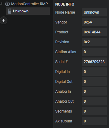
    NodeInfoDetails

2. Editing CustomNodeInfo.xml

  • CustomNodeInfo.xml, included in all our releases, contains examples for customizing nodes.
  • Add a new entry in the <Vendors> block like this:

    <Vendor Id="0x6A">
    <VendorName>Example Vendor</VendorName>
    <Product Code="0x414b44">
    <ProductName>Example Product</ProductName>
    <ShortName>Our Node Name</ShortName>
    <ItemSubType>Box</ItemSubType>
    <!-- Add AxisCount only if appropriate, otherwise Delete it. -->
    <AxisCount>1</AxisCount>
    </Product>
    </Vendor>
Note
The 6A and 414b44 were pulled from the Node Info above. You can use any description string for <VendorName>, <ProductName>, and <ShortName>. ShortName is what you will see in RapidSetup replacing Unknown. The <ItemSubType> can be Box, Term, or Drive with no change in behavior. Its a description that is added to each PDO entry.

3. Copy the new ESI file to the ESI folder

  • Copy the ESI file to the ESI folder in the RapidCode installation directory.
  • The ESI file is provided by the manufacturer.

4. Generate the ENI file and start the network

Bonus: DS402 Auto Implementation

  • For DS402 Drives, RMP auto-detects and configures common parameters like ControlWord, StatusWord, Position Actual, Position Demand, Velocity Actual, Velocity Demand, Torque Actual, Target Torque, and Position Error.
  • You can customize further in CustomNodeInfo.xml, but it's not required.
  • Any CustomNodeInfo.xml entry will override automatically detected entries.