|
APIs, concepts, guides, and more
|

|
APIs, concepts, guides, and more
|
Determine if your hardware meets the requirements for running RMP.
If you're using an RSI Industrial PC , you can skip the rest of this page—your PC is already fully compatible with RMP. These systems are pre-vetted to ensure optimal real-time operating system (RTOS) performance, including low latency, minimal jitter, and guaranteed RMP compatibility.
Tenasys INtime RTOS will be installed, as described in Install RMP for Windows.
A PREEMPT_RT enabled kernel is required for real-time performance on Linux.
RSI recommends Intel CPUs with the TCC feature for the best real-time performance. See the Intel TCC CPU list.
For a detailed list of compatible CPUs, refer to the Tenasys INtime CPU list..
The RMP requires at least one network interface card (NIC) to communicate with EtherCAT devices. The NIC must support 100 Mbps or greater.
| Supported NICs | INtime Driver |
|---|---|
| Intel 10/100Mbps | ie100m |
| Intel 1Gbps | ie1g |
| Intel 82575/82576/82580 | ie1ge |
| Intel 2.5Gbps i225/i226 | ie25g |
| Realtek 10/100Mbps | rtl100m |
| Realtek 1Gbps | rtl1g |
For a more extensive list, including hardware IDs, visit Tenasys Supported network interface card list. (RMP-Windows requires INtime HPE support for the NIC driver.)
Latency refers to the time delay between the instant a task is scheduled and the moment the system starts executing the scheduled task. Jitter refers to the deviation from the expected timing behavior. Low latency and jitter are crucial in real-time systems, like those controlling machinery, to ensure tasks are executed quickly and predictably. In systems using EtherCAT, excessive jitter can disrupt the network or impact performance.
Performing a measurement of maximum latency and jitter is crucial for evaluating hardware for RMP.
RMP will precisely schedule EtherCAT frames (RMP Sample Rate) so your RTOS maximum latency is critical. Maximum latency is determined by running high-priority cyclic threads and measuring how long the thread takes (worst-case) to wake and respond. RMP will adjust EtherCAT nodes to process the data as far as possible from when RMP sends the data. This refers to how frequently the RMP updates the system's motion.
Guidelines for maximum acceptable latency:
| RMP Sample Rate | Recommended | Acceptable |
|---|---|---|
| 500Hz | 250us | 500us |
| 1000Hz (default) | 125µs | 250µs |
| 2000Hz | 62.5µs | 125µs |
| 4000Hz | 31.25µs | 62.5µs |
The optimal system should have no more than 40µs deviation from the Average Tick value.

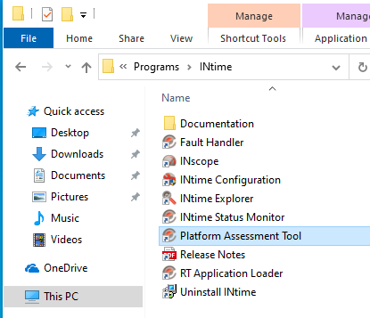
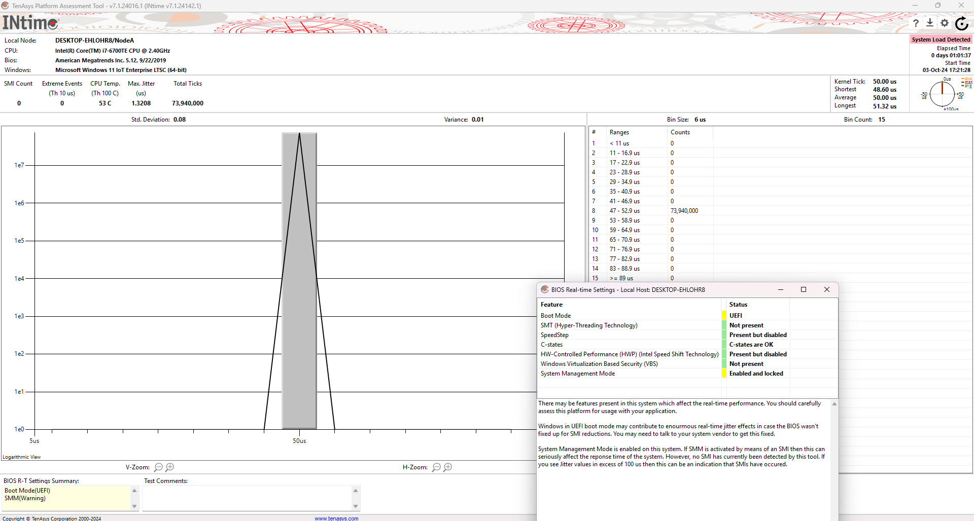
Navigate to C:\Program Files (x86)\INtime\bin\tpat.exe and open the application Platform Assessment Tool. Select NodeA and click Start. A good way to simulate demand is to run two long YouTube videos in the background during the Jitter test. Let the tool run overnight to gather enough data. The tool displays CPU information, timing records, and a histogram.

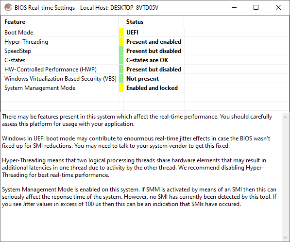
Two key indicators are Max Jitter and Longest Tick. Consistently low Longest Tick values are more critical than the Shortest Tick values for smoother operation. Excessive jitter can lead to "motor knocking," impacting the precision of machinery. Refer above for RSI recommended values. If you are unsatisfied with your results, Platform Assessment Tool provides a brief summary of BIOS Real-time Settings that may be configurable, detailed below.
To measure latency and jitter on Linux systems, use the rmp-eval tool, an open-source utility designed specifically for evaluating PC hardware compatibility with RMP. The tool requires root access and a PREEMPT_RT kernel.
Pre-built packages for amd64 and arm64 are available from the rmp-eval GitHub releases. On Debian/Ubuntu:
For CPU-only latency testing:
For testing with network interface (requires a connected EtherCAT drive):
Press Ctrl+C to stop the test and view results. Let the tool run for several minutes or longer to capture worst-case scenarios. Running demanding applications (like video playback) during testing can help simulate real-world load.
Label: Thread type - Sender and Receiver (when using --nic), or Cyclic (CPU-only mode)
Count: Total number of test cycles completed
Latency Buckets (< 125µs, < 250µs, < 500µs, < 1000µs, >= 1000µs): How many cycles had timing deviations in each range. Color-coded by severity (green = excellent, red = poor). All cycles should ideally fall in the first bucket.
Max Latency: Worst-case latency deviation observed. Compare this value to the Maximum acceptable latency table above based on your target RMP sample rate.
Ideally, all observations should fall in the first bucket (< 125µs for 1kHz operation).
The traditional cyclictest tool can also be used for latency measurement:
Where -p 45 sets the real-time priority (matching RMP's default max priority), -a 3 specifies the isolated CPU core, and -i 1000 sets the timer interval to 1000 microseconds (1kHz sample rate). For faster sample rates, adjust the interval accordingly (e.g., 4kHz = -i 250).
For cyclictest users: compare the Max value in cyclictest output to the acceptable latency values in the table above.
For optimal real-time performance on Linux, one CPU core must be isolated and dedicated exclusively to RMP operation. This isolated core runs the RMP real-time thread without interference from other system processes.
The rmp-eval tool automatically checks your Linux system configuration and reports potential issues. When you run the tool, it displays comprehensive system, CPU core, and network interface checks:
System Checks:
Core Isolation Checks:
NIC Checks (when using –nic):
For detailed information about rmp-eval and its configuration checks, visit the rmp-eval GitHub repository.
The INtime Platform Assessment Tool offers a detailed overview of BIOS configurations that may impact real-time performance. The BIOS Real-Time Settings Summary is available in the lower-left corner of the Platform Assessment tool. By double-clicking this section, users can access detailed information regarding each setting.

| Setting | Description |
|---|---|
| Hyper-Threading / SMT | Hyper-Threading (Intel) and SMT (AMD) allow two threads to share CPU resources, which can lead to one thread waiting for shared resources, increasing jitter. Disabling Hyper-Threading or SMT can improve real-time performance by eliminating this contention, though it reduces the total number of logical processors available. |
| SpeedStep / CPPC | Intel SpeedStep and AMD CPPC dynamically adjust CPU frequency to save power, which can increase latency and jitter. Disabling these features helps ensure the CPU runs at a constant frequency, improving predictability in real-time systems. |
| C-States / Cool'n'Quiet | C-States (Intel) and Cool'n'Quiet (AMD) allow the CPU to enter lower power states, where the clock may slow down or stop. This can increase latency when the CPU must wake up to handle tasks. Disabling C-States/Cool'n'Quiet in the BIOS prevents the CPU from entering these power-saving modes, ensuring consistent performance. |
| HWP (Intel Speed Shift Technology) | Gives the CPU control over power management, allowing it to change power consumption and frequency dynamically, which can negatively impact real-time performance. Disabling HWP can prevent these frequency changes and improve jitter. |
| System Management Mode (SMM) | SMM is a special operating mode where the CPU temporarily suspends normal operation to handle low-level system management tasks. While in SMM, the CPU cannot handle regular interrupts, leading to large spikes in latency (jitter). Reducing or eliminating SMM usage in the BIOS is critical for real-time performance. |
| Turbo Mode / Precision Boost | Intel Turbo Mode and AMD Precision Boost allow the CPU to increase clock speeds beyond its base frequency, potentially increasing jitter. Disabling Turbo Mode/Precision Boost can help keep the CPU frequency stable, reducing variability in execution time. |
| Spread Spectrum | Modulates the CPU clock frequency slightly to reduce electromagnetic interference (EMI), but this can introduce small fluctuations in timing and increase jitter. Disabling Spread Spectrum helps maintain a stable clock for real-time performance. |
| TSC Sync | Ensures the Time Stamp Counter (TSC) is synchronized across all CPU cores. Unsynchronized TSCs can cause timing inconsistencies in real-time systems. |
| NUMA | In multi-socket or large-core systems, NUMA can improve memory access speed but may increase latency if not properly configured. For real-time systems, disabling NUMA or carefully binding tasks to a single NUMA node can reduce latency and jitter. |
| PCIe ASPM | PCIe Active State Power Management (ASPM) reduces power consumption by placing devices in lower power states. Disabling ASPM in the BIOS ensures PCIe devices maintain their performance, reducing latency when waking from low-power states. |
| SATA Power Management | Similar to PCIe ASPM, SATA power management introduces delays when accessing disks after they’ve entered a low-power state. Disabling SATA power management improves performance consistency. |
Please note that the availability and configuration of these BIOS settings vary depending on the motherboard and BIOS manufacturer.